Triaxial shear strength test on soil measures the mechanical properties of the soil. In this test, soil sample is subjected to stress, such that the stress resulted in one direction will be different in perpendicular direction. The material properties of the soil like shear resistance, cohesion and the dilatancy stress is determined from this test. The test is most widely used and is suitable for all types of soils.
Triaxial Shear Test Apparatus
The important apparatus for triaxial shear test are:
- Triaxial testing machine complete with triaxial cell : This unit have the provision to insert a cylindrical soil specimen that is sealed by means of rubber membrane to restrict the entry of lateral fluid. Radial fluid pressure and the vertical stress is applied by means of a piston arrangement. The unit also have the provision to prevent the drainage of specimen. The fluid pressure in the cell can be measured by means of a pressure gauge.
- Equipment for loading
- Equipment to measure load and Deformation : Proving is used to measure the load application by the piston. A dial guage is used to measure the deformation of the specimen
Triaxial Shear Test Principle
A cylindrical specimen, generally having a length to diameter ratio of 2, is used in the test and is stressed under conditions of axial symmetry in the manner shown in figure below.

Fig.1:Schematic Diagram of stress system at soil during triaxial test

Fig.2: Triaxial Test Apparatus
The normal size of the sample will be 76mm x 38mm & 100mm x 50mm. The sample is subjected to three principal stresses. Among this three stresses, two are stress due to water pressure that is within the confining cell. The two values are equal.
The application of a load on the top of the cell by means of a ram as shown above, is the applied third stress. This stress is different from other two stresses.
The sample tested has its ends sealed by top cap and bottom pedestal by rubber O-rings. If these involves pore pressure measurement, porous stones can be placed at the bottom and the top of the specimen.
Pressure transducers are used to measure the pressure that is developed inside the specimen.
The triaxial shear testing can be conducted by two steps:
Step 1: The soil sample is prepared and set in the triaxial cell. Then the confining pressure is applied.
Step 2: Here, deviator stress is applied, which is an additional axial stress. This induces shear stresses within the sample. The axial stress applied is increased till the soil sample fails.
The applied stresses, axial strain and the pore water pressure is measured for both the above steps.
Triaxial Shear Test Procedure
The specimen can be prepared either remoulded or undisturbed. Undisturbed soil can be tested on soils that have sufficient cohesion. In order to make remoulded soils, cohesive soil is collected and compacted properly. Care is taken while preparing the cohesion less soils.
The triaxial shear test can be conducted in different variations. The most commonly employed types are:
- Unconsolidated Undrained Test (UU)
- Consolidated Undrained Test (CU)
- Consolidated Drained Test (CD)
1. Unconsolidated Undrained Test (UU)
As the name tells, the soil sample is subjected to cell pressure with no provision of drainage. Here the cell pressure is maintained to a constant value and the applied deviator stress is increased till the sample fails. This is called as quick test.
2. Consolidated Undrained Test (CU)
Here, during the application of cell pressure on the sample, drainage is permitted. And the deviator stress is applied keeping the cell pressure constant and no provision of further drainage.
3. Consolidated Drained Test (CD)
This test is also called as drained or slow test. Here the deviator stress is increased by allowing the drainage to happen as it was and the cell pressure is also kept constant. Here the rate of loading is applied slowly so that excess pore pressure is not developed within the sample
The prepared specimen is enveloped in the membrane and positioned in the triaxial cell. To this, the desired lateral pressure is applied. Till the specimen fails, the lateral pressure is applied. The vertical deformation and the load readings are recorded.
The main objective of the test is to determine the values of cohesion and angle of internal friction. To determine these values, three different lateral pressure values have to be tested on the sample.
Calculations
The test specimen is subjected to all around lateral pressure (

). The deviatric stress applied be

. Then total vertical stress is
 ,
,
A mohr’s circle is drawn by plotting
and
in x- axis and the shear stress is the y-axis. Mohr’s rupture envelope is obtained by drawing the tangent to the circles obtained. The tangent will intercept at the y-axis. The y intercept will give the value of cohesion (
C). The slope of the failure plane or the tangent line will give the angle of internal friction of the soil ( ø).
The loading can increase the cross section of the soil specimen. This will require a correction for the deviatric stress
. Here, the correction is applied by assuming that the volume of the specimen remain constant and the area varied. The corrected deviatric stress is
P1 = Applied Load
Ao = Original Area of cross section
l0 = Specimen Original length
l = deformation of the specimen
The shear resistance of the sample is given by:
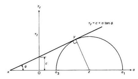
Fig.3: Determination of Stress parameters by Mohr’s Circle
Effective Stress Conditions
The effective stresses acting on the soil specimen during testing are shown in figure. In this case effective minor principle stresses is equal to the cell pressure (fluid pressure) minus the pore pressure. The major principle stress is equal to deviator stress plus the cell pressure. Hence, the effective major principle stress

is equal to the major principle stress minus the pore pressure.
Let the stress components on the failure plane MN be

and

and the failure plane is inclined at an angle

to the major principle plane.

Fig.4.Effective Stress Determination by Mohr’s Circle
Let the envelop DF cut the abscissa at angle

, C be the centre of the Mohr’s circle.
From

and

we get,
Principle stresses relationships at failure
OC =

OF =

Again from

,
On solving this equation, we get
But

Therefore,

From the Mohr’s circle drawn, the straight line forms the failure plane and the intercept created is the effective strength parameter c’ of the soil. The angle made by the plane ø’ forms the angle of friction.Hence, effective shear strength is given by
Pore water pressure measurement
Pore water pressure must be measured under conditions of no flow either out of or into the specimen, otherwise the correct pressure gets modified. It is possible to measure pore water pressure at one end of the specimen while drainage is taking place at the other end. The no flow condition is maintained by the use of the null indicator, essentially a U-tube partly filled with mercury.